
Construction 2026 · Primer
How concrete 3D printing actually works
Gantry and arm machines, the mixer-pump-hose-nozzle chain, bead geometry, layer timing, cold joints, and cure, plus what a wall demo does and does not prove.
- Level
- Intermediate
- Reading time
- 14 minutes
- Evidence
- standards-and-company-reported
- Reviewed
- 2026-08-09
Jump through this guide
The short version
Construction-scale concrete printing replaces formwork with flow control. A mixer, pump, hose, and nozzle deliver a mortar bead that must hold its shape in seconds, carry the next layer in minutes, and bond into a wall meant to last decades. This primer follows the machine families, the material chain behind them, bead geometry, layer timing, and cure, then separates what a demonstration wall proves from what building codes actually require, drawing throughout on the overview of 3D concrete printed construction practices prepared for the U.S. Department of Housing and Urban Development 1.
After reading, you can
- Name the five construction-printer architectures and the site logistics each implies
- Trace the material chain from mixer to nozzle and identify where it can fail
- Explain how bead geometry, layer timing, and cold joints govern wall quality
- Distinguish what a wall demo demonstrates from what codes and standards evaluate
01
One process, five machine shapes
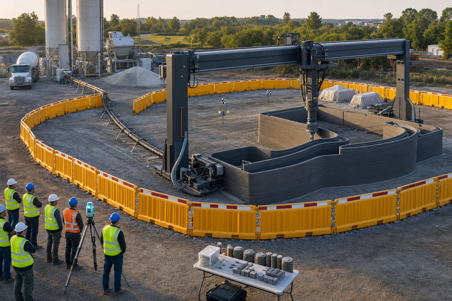
A construction printer is an extrusion system scaled to a building lot: a motion platform steers a nozzle, and pumped mortar leaves it as a continuous bead. The federal overview of 3D concrete printed construction, prepared for HUD by Home Innovation Research Labs, identifies five machine architectures in current use: gantry, robotic arm, robot crawler, polar, and delta 1. The gantry, a frame that spans the work and carries the printhead above it, is described there as the most widely used type in the industry, and among the most capable of printing openings by starting and stopping flow 1.
The other shapes trade print envelope for mobility. Arms and crawlers move by trailer and reposition inside a floor plan; a polar machine sweeps a boom around a mast; a delta suspends its head from a surrounding frame 1. Manufacturers describe the same split in their own terms. COBOD reports modular gantry systems used for buildings up to three stories 5, Apis Cor reports compact mobile robots that print structural walls up to two stories 6, and Constructions-3D reports a foldable unit that stows to eighty-six centimeters wide and exits the finished building through a standard door 7.
- Gantry: frame spans the building; largest envelope, heaviest logistics
- Robotic arm: compact and repositionable; limited reach per setup
- Robot crawler: tracked base; drives itself between print positions
- Polar: boom sweeps around a mast; prints within its radius
- Delta: overhead frame; historically favored for earthen mixes
02
Follow the material, not the robot
Every system runs the same supply chain: a mixer wets the material, a pump pushes it through a hose, and the nozzle meters it onto the wall. The HUD overview lists the supporting cast a highlight reel usually crops out: material and water supply, an operator running the pump, a laborer feeding it, and an inspector watching the wall rise 1. The wall records every stumble in that chain; the report's own procured test wall showed voids where pump flow faltered, assessed and corrected during later grouting 1.
Feed philosophies differ, and companies state them plainly. COBOD reports that its printers run on locally sourced concrete with aggregates up to ten millimeters, avoiding proprietary bagged material 5. Black Buffalo's system, described in the same federal overview, takes the opposite route: a proprietary dry ready-mix that needs only site water 1. ICON describes a vertically integrated suite in which printer, dedicated pump, on-site mixer, material, and orchestration software ship as one system 8. Each answer moves cost, control, and quality responsibility somewhere different, which is why the material chain, not the robot, is the real product.
03
The bead is the unit of construction
Watch one bead instead of the whole machine. Its width and height are set by nozzle geometry, flow rate, and travel speed; its cross-section is a flattened oval; its edges become the layered texture printed walls are known for. Stacked beads form a shell, and shells form wall systems: one thick extrusion, parallel beads bonded side by side, or two printed face shells serving as stay-in-place formwork for a reinforced core. The ICC 1150 standard for printed concrete walls explicitly covers single-shell, multi-shell, and reinforced-core configurations 4.
Toolpath design is therefore structural drafting. Corners must turn without starving or doubling the bead; openings need starts and stops the machine can execute cleanly; the path must return to each layer's beginning before the material below stiffens past bonding. Curves appear everywhere in printed architecture partly because a curved run of fresh material stands more stably than a long straight one, and partly because curvature costs a printer nothing extra. What reads as style is, first, a record of flow control.
- Bead size: nozzle, flow rate, and travel speed
- Stacking: beads to shells, shells to wall systems
- Corners: flow control decides crisp or collapsed
- Openings: printed by planned starts and stops
- Texture: the layer record most projects choose to keep
04
The layer clock: timing, cold joints, cure
Between one layer and the next, a clock runs. Return too soon and the lower bead deforms under new weight; return too late and its surface has stiffened and dried past intimate bonding, leaving a cold joint, a weak seam disguised as an ordinary layer line. Layer timing is thus a scheduled quantity: path length, speed, and pauses set the interval, and the mix must be designed to accept it. ICC 1150 treats interlayer bonding, load transfer, and structural continuity as defining characteristics of layered walls, with requirements written specifically for them 4.
Cure extends the timeline past the final layer. A printed wall stands without formwork from its first minute, so sun, wind, and frost reach young concrete that conventional construction keeps covered. Producers therefore prescribe curing and protection procedures, and quality frameworks make following them auditable: ISO/ASTM 52939 sets quality-assurance requirements across the whole additive-construction operation, independent of the particular material or machine 2. The HUD overview's inspection checklist ends on the same blunt question: has the printed structure been cured as the manufacturer prescribes 1?
05
Setup, site, and the parts nobody films
Machine architecture decides site logistics. The HUD overview walks through what a gantry brings: frame modules on semi-trailers, assembly and leveling, sometimes footers or slab aprons to carry the moving mass, and a lot with room around the footprint 1. Compact machines trade that overhead for repositioning cycles inside the plan, roughly three-quarters of an hour per move in the report's accounting 1. Vendors compete on exactly this: Constructions-3D reports container delivery and site deployment in as little as fifteen minutes, a figure readers should treat, like all vendor figures here, as company-reported 7.
Then the rest of construction arrives. Printed shells still need foundations tied to walls, lintels or engineered openings, roof connections, insulation, services, and finishes; the HUD team documents foundation-to-wall details, window and door installation, and utility routing as the places where printing meets everything else, and where early mockups leaked or fought the trades until details matured 1. Apis Cor frames its own systems as printing structural walls, one scope within a whole building 6. The robot is the easiest part to photograph and the smallest part of the schedule.
06
What a wall demo proves, and what it does not
A finished demonstration wall proves real things: the mix pumped, the bead stacked, the geometry closed, the crew executed. It does not prove code compliance, capacity under design loads, durability across seasons, fire behavior, or cost; those live in test data, engineering, and documents. The evaluation infrastructure for them now exists. ICC-ES operates acceptance criteria for 3D concrete walls, evaluating material and durability properties, structural performance, and fire resistance of proprietary systems 3, and ICC 1150-2026 carries the approach into a published standard covering materials, qualification, inspection, and structural design 4.
The distinction matters most for readers. When a video shows a wall rising, the productive questions are: what mix, what layer interval, what reinforcement, what happens at openings, who inspected, and against which document? ISO/ASTM 52939 exists so that an additive-construction project can answer with records rather than adjectives 2. The next articles in this series follow those questions into the material system and the code path. A demo is an invitation to ask; it was never the answer.
- Shown: pumpable mix, stackable bead, executable geometry
- Not shown: design capacity, durability, fire performance
- Not shown: code approval, inspection records, insurance
- Ask: mix, interval, reinforcement, openings, documents
- Standards name the evidence a claim requires
Working vocabulary
Glossary
- Gantry printer
- A construction printer whose printhead moves on a frame that spans the work area from above.
- Bead
- The continuous ribbon of extruded material a nozzle deposits in one pass.
- Face shell
- A printed outer wall skin, often paired with a second shell and a filled core.
- Cold joint
- A weak interface formed when new material is placed against material that has stiffened too far to bond.
- Layer interval
- The elapsed time between depositing one layer and the next at a given point on the wall.
- Open time
- The period during which placed material can still bond properly with the next layer.
- Toolpath
- The programmed route the nozzle follows, including starts, stops, and corner moves.
Source ledger
References and further study
Numbered citations point to the sources below. We favor standards, government laboratories, peer-reviewed research, and primary technical documentation. A link is evidence for the claim it supports—not an endorsement of every claim on that website. Read the full editorial and correction method.
- 3D Concrete Printed Construction Systems, Part 2: An Overview of 3DCP Construction PracticesU.S. Department of Housing and Urban Development, Office of Policy Development and Research · government research report↗Opens in a new tab
- ISO/ASTM 52939:2023 — Additive manufacturing for construction — Qualification principles — Structural and infrastructure elementsInternational Organization for Standardization · international standard↗Opens in a new tab
- 3D PrintingICC Evaluation Service, LLC · building-product evaluation program↗Opens in a new tab
- ICC 1150-2026: Standard for 3D Automated Construction Technology for 3D Concrete WallsInternational Code Council · construction standard↗Opens in a new tab
- 3D Construction Printing TechnologyCOBOD International · company-reported information↗Opens in a new tab
- Apis Cor - Robotic Construction TechnologyApis Cor Inc. · company-reported information↗Opens in a new tab
- MaxiPrinter | Concrete 3D PrinterConstructions-3D · company-reported information↗Opens in a new tab
- Titan Construction System for Large-Scale 3D PrintingICON Technology, Inc. · company-reported information↗Opens in a new tab